FEARCE - Thermal analysis for IC engines

FEARCE-Vulcan uses a unique iterative Finite Element (FE) solution that considers all the heat paths in detail to calculate the thermal boundary conditions of the power cylinder components using physical models and semi-empirical correlations, without the need for CFD analysis. This overcomes the limitation of database methods which are not predictive and delivers a reliable and accurate predictive tool for conclusive structural investigations.
The iterative solution runs quickly enough to allow different design variants to be assessed for multiple operating conditions. The calculated temperatures and the corresponding deformations can then be used to predict piston secondary motion and ring dynamics and to better predict friction, wear and oil consumption of the power cylinder and the structural durability of the components.
Thermal modelling of more efficient and lower emission IC engines
As IC engines become smaller, often in a hybrid system, this requires higher peak cylinder pressures to improve fuel economy, which drives higher in-cylinder temperatures. Analytical tools are required to optimize the design to deliver more durable components, whilst minimising extensive testing to reduce product development costs.
Thermal survey measurements are an important part of engine development and are used together with CFD to predict component temperatures. However, these measurements and analytical methods can be costly, time and labour intensive, and in the case of the measurements require a physical engine.
FEARCE-Vulcan can be used early in product development before hardware exists reducing CFD and thermal survey costs making the engine development cycle more efficient. This new tool also meets the future challenges of ICE design and development, by accurately predicting the thermal loading and temperatures of an ICE quickly under multiple full-load and part-load conditions.
Thermal models
In-cylinder
The in-cylinder model generates thermal boundary conditions considering the heat transfer between the cylinder gas and surrounding components exposed to the cylinder gas - namely the piston crown, cylinder wall, cylinder head flame face and the flame faces of each valve.
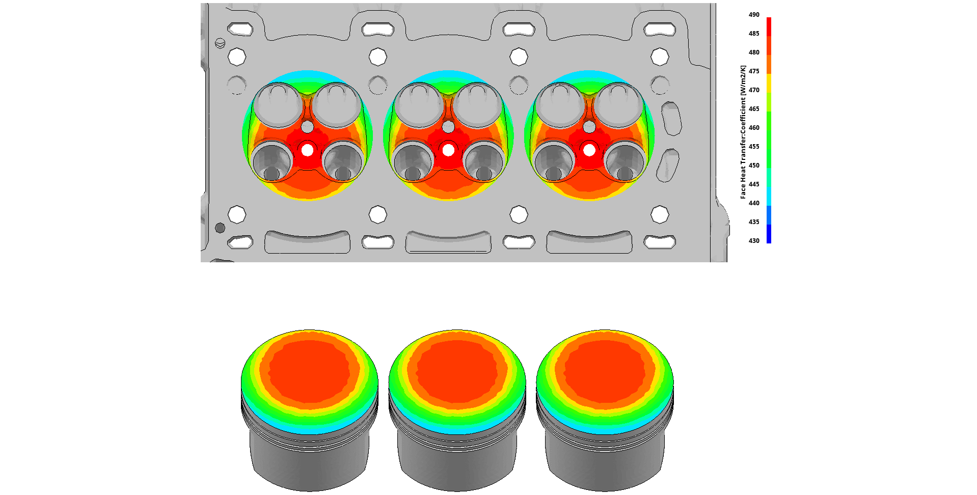
Piston crown and flame face boundary conditions are based on the propagation of burned gas during combustion. Spatial variation of gas temperature is determined using a two-zone combustion model by splitting the average temperature into temperatures of burnt and unburnt zones, to calculate for each point on the surface its exposure to each zone.
Valve
The valve model generates thermal boundary conditions from the convective heat transfer between the valve, cylinder and port gases, together with the heat transfer between contact interfaces, namely the seats and guides.
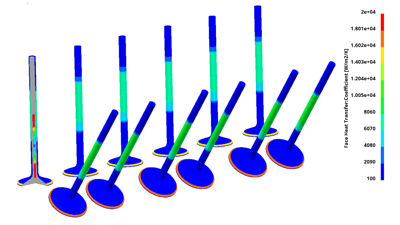
All the necessary heat transfer mechanisms are considered including:
- Gas load on the valve head
- Gas flow over the back face
- Gas flow around the stem
- Oil film conduction to the guide
- Seat contact when the valve is closed
- Gas flow over the seat when the valve is open
For those surfaces of the valve exposed to the gas in the cylinder, the in-cylinder model calculates the thermal loads and projects them onto the exposed valve surfaces. For sodium cooled valves the sodium temperature is simulated as part of the iterative solution.
Piston to liner interface
The piston to liner model considers ring dynamics and piston secondary motion to generate thermal boundary conditions, considering heat transfer between the piston rings and liner, as well as the piston skirt and liner.
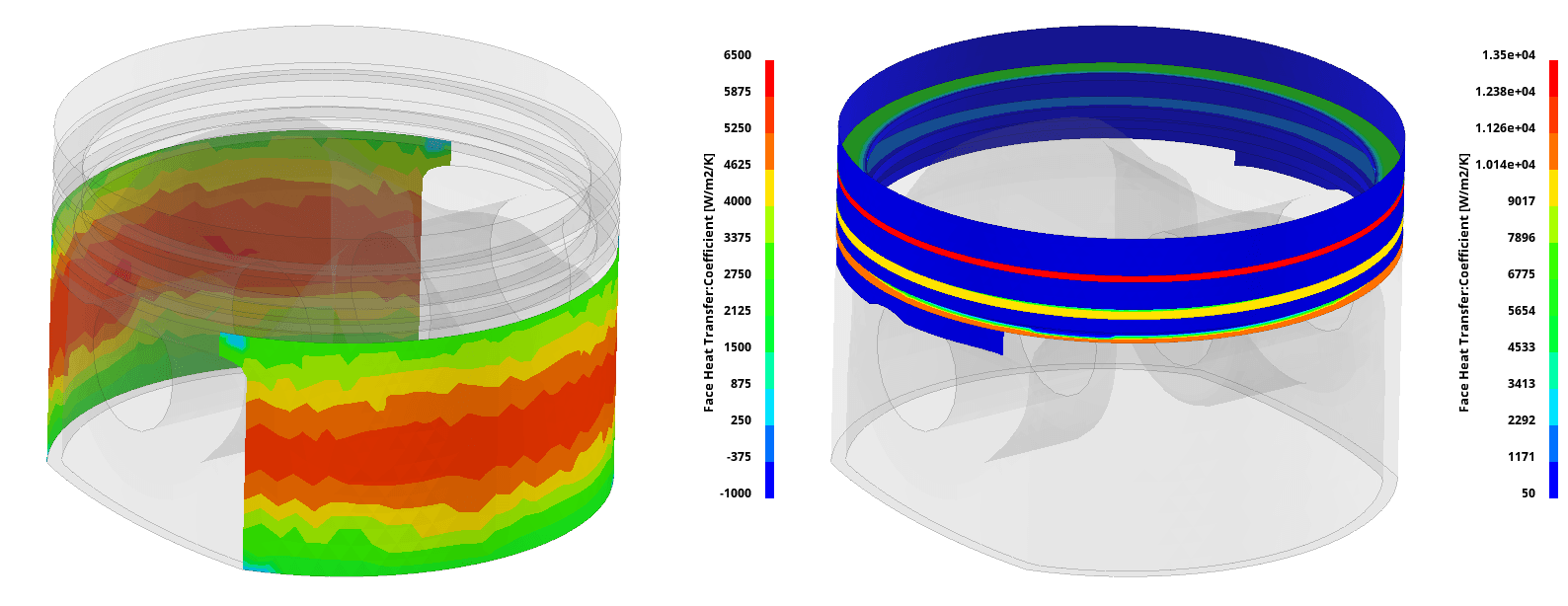
Piston secondary dynamics and piston rings' dynamic models are automatically generated from the supplied geometric and FE data to calculate clearances and heat transfer between the skirt, rings, piston grooves and liner. The heat transfer data are mapped and cycle-averaged onto the FE models of the piston and cylinder bore.
Piston cooling
The piston cooling model considers cooling mechanisms due to piston cooling jets, gallery cooling and crankcase oil.
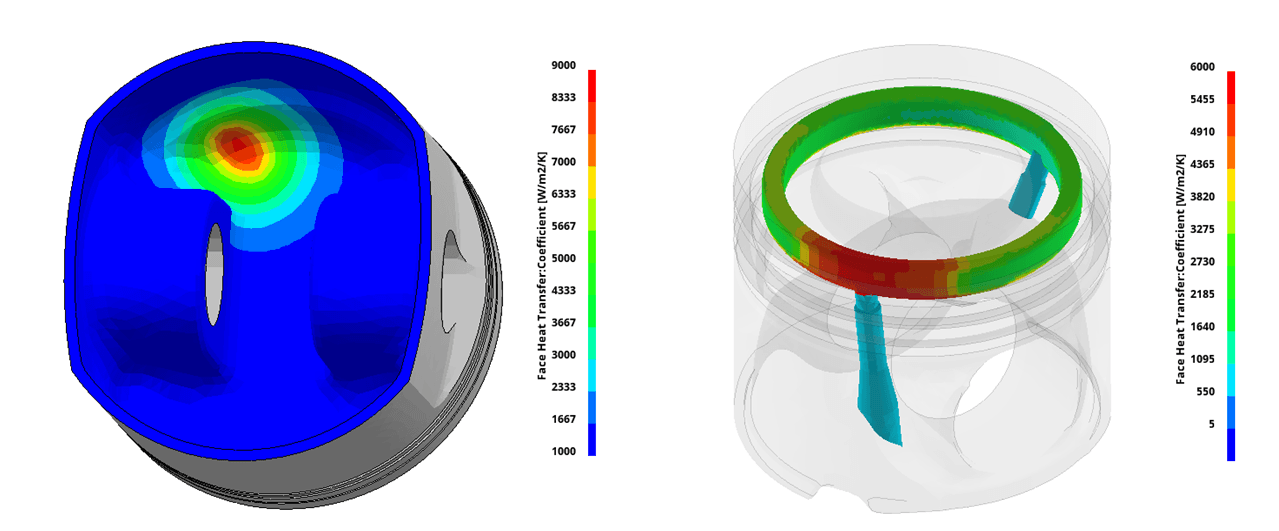
The piston cooling jet model requires as input the position, angle of each jet and oil supply boundary conditions. The model considers the following features to derive the thermal boundary conditions:
- Impingement durations
- Spatial variation due to the jet spreading
- Varying impingement location
- Asymmetric flow due to compound impingement angle
Cylinder bore
Cycle-averaged boundary conditions are applied to the cylinder bore due to in-cylinder combustion and piston thermal loading via the ring pack and skirt, together with cooling due to the oil.
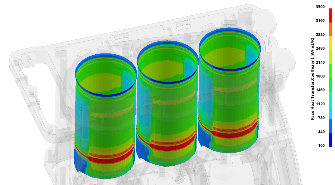
Boundary conditions due to flow of the coolant are either applied as constant HTC and fluid temperature values to the surfaces defining the water jacket, or mapped from an isothermal CFD analysis of the coolant circuit.
The effect of nucleate boiling is simulated as part of the iterative solution using a map of heat transfer coefficients dependent on the resultant wall temperature. In the locations where the resultant wall temperature is predicted above the boiling point, the heat transfer coefficient is adjusted (increased) and used for the next iteration.
Key features
- All heat paths of the power cylinder are considered
- Dedicated graphical user interface
- Supports Diesel, gasoline, natural gas and hydrogen combustion
- Optionally CFD combustion boundary conditions can be included as part of the FEARCE-Vulcan process
- Automatic generation of piston and piston rings' dynamic models with appropriate defaults
- Support of sodium cooled valves
- Piston cooling due to piston cooling jets (PCJ) and those pistons with a gallery are considered
- The effect of nucleate boiling on the engine coolant side is included
- The Realis Run Distribution Manager (RDM) allows cases to be run in parallel delivering thermally efficient IC engines in ever-shorter timescales
